Understanding how to align coordinates in space and time is crucial for high-precision GNSS and real-time kinematic (RTK) solutions. This article explains the core concepts of reference frames, epochs, and coordinate transformations which are essential for achieving precise positioning in GNSS applications. For a more detailed overview with worked examples and mathematical background, read our white paper: Practical Notes on Coordinate Transformation.
Executive Summary:
What is a Datum?
- A datum (or reference frame) is a coordinate system that defines positions on Earth, accounting for its shape, orientation, and size.
- It enables a standardized way to specify locations by considering Earth’s dynamics, like tectonic shifts, which affect long-term positioning accuracy.
Why Datums Matter:
- Precision in Positioning: Accurate positioning depends on choosing a datum that aligns with the location’s regional and global characteristics. Using the correct datum prevents errors when translating satellite data into ground-based coordinates.
- Coordinate Transformations: GNSS systems typically use global datums (e.g., ITRF2020) that must be transformed to local datums (e.g., NAD83) to account for tectonic plate movement. These transformations ensure data consistency and accuracy across geographic areas.
Differences Between Datums:
- Global Datums (e.g. ITRF2020, WGS84): Provide a worldwide framework but don’t account for local tectonic shifts. Useful for global navigation and satellite positioning.
- Local Datums (e.g. NAD83, ETRS89): Regional frames tied to specific areas, adjusted for local tectonics to provide stable positioning over time in a given region.
- Epochs: Datums are often associated with an epoch (a specific time) because the Earth’s surface is always moving. Adjustments between epochs help maintain accuracy as coordinates shift over time.
Practical Application:
- GNSS and RTK positioning rely on accurate datum selection and transformations for precise, real-time navigation, especially in high-precision fields like surveying and autonomous robotics.
The Role of Reference Frames and Coordinate Transformations for RTK Solutions
Coordinate transformations and reference frames are critical in Real-Time Kinematic (RTK) positioning for achieving precise, reliable, and repeatable results. RTK relies on satellite-based signals to determine positions in real time and corrections are delivered in a particular reference frame, depending on the service provider. In our own precise positioning service, Skylark, we offer a broad range of frames to choose from including ITRF2020, WGS84, NAD83, ETRS89, and more.
In this article we will cover the concepts behind reference frames (datums), coordinate transformation and temporal (epoch) changes. Here’s why they matter for RTK:
1. Reference Frame Conversion: RTK systems calculate positions based on satellite signals that use global reference frames like ITRF (International Terrestrial Reference Frame). These reference frames account for Earth’s shape and dynamics. However, local reference frames, like NAD83 in North America, are often used to account for regional tectonic plate movements. Without aligning these reference frames, RTK positioning would yield errors when converting satellite data into useful ground-based coordinates.
2. Coordinate Transformation: Since different reference frames exist, a coordinate transformation is necessary to translate GNSS satellite positions into the desired local coordinate system used by surveyors or engineers. For example, transforming from an ECEF frame to a local geodetic frame ensures the RTK-derived coordinates match the local ground reality, accounting for plate tectonics or datum shifts.
3. Temporal Changes: Reference frames like ITRF are time-dependent due to tectonic movement, meaning the coordinates of fixed points change over time. RTK systems must transform coordinates with respect to both spatial and temporal shifts, ensuring long-term precision, especially in areas experiencing high tectonic activity.
Using the correct coordinate transformation and reference frame ensures that RTK delivers highly accurate and relevant location data, avoiding positional discrepancies caused by tectonic shifts or mismatched reference systems.
Introduction to Coordinate Systems and Reference Frames
Expressing Location on Earth
Before delving into the topic of geodetic reference frames, alternatively known as geodetic datums, we must first understand how Earth-based coordinate systems work. There are three main ways to express one’s location on our planet: Cartesian, Geodetic, and Map Grid coordinate systems.
Cartesian Coordinates
The simplest way to express the location of an object on Earth is to use the 3D Cartesian axes (x,y,z). The advantage of the Cartesian system is that the three components of the position vector are expressed in linear units (meters), allowing all position-related calculations to be performed using vector geometry. However, its disadvantage lies in the non-intuitive nature of Cartesian coordinates, as it is difficult to conceptualize location in this form due to the lack of clear ‘horizontal’ and ‘vertical’ components.
Geodetic Coordinates
A geodetic (or geographic) coordinate system represents positions using latitude, longitude, and height (altitude), denoted as (𝜙, 𝜆, ℎ). These coordinates are defined by the normal line to the ellipsoid at any given point. Latitude is the angle between this normal and the equatorial plane, while longitude is the angle between the prime meridian (Greenwich) and the meridian containing the normal. The ellipsoid height measures the distance along the normal from the ellipsoid surface to the point in question.
The geodetic system’s advantage lies in its intuitive visualization of locations on Earth. However, its drawbacks include the use of curvilinear coordinates (degrees) and the complexity of performing spatial calculations on the ellipsoid’s surface. For example, determining the distance between two points based on latitude and longitude is less straightforward than calculating vector distances in Cartesian coordinates, despite often being more practically meaningful.
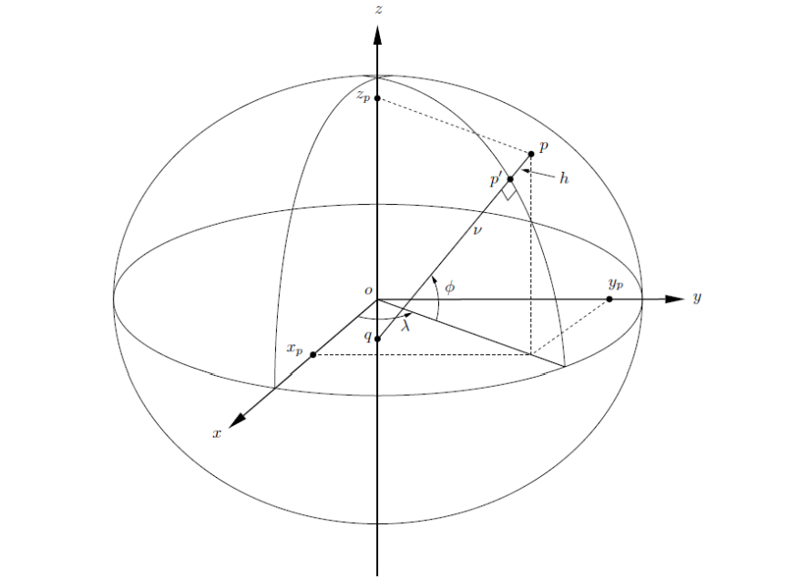
Figure: The Cartesian (x,y,z) and geodetic (𝜙, 𝜆, ℎ) coordinate systems
Map Grid Coordinates
To avoid the complexity of working on the curved surface of the ellipsoid and the non-intuitive nature of Cartesian coordinates, planar or map grid coordinates are often used. These coordinates are obtained by applying the appropriate map projection formulas to the corresponding geodetic coordinates. While various map projections exist, the Transverse Mercator (TM) and Universal Transverse Mercator (UTM) projections are most commonly used. Map grid coordinates are typically represented as (𝐸, 𝑁, ℎ).
The advantage of the map grid system lies in its planar nature, which simplifies calculations. However, every map projection introduces some form of distortion (e.g., in scale, area, or orientation), which must be accounted for in spatial calculations, adding complexity and potential for error.
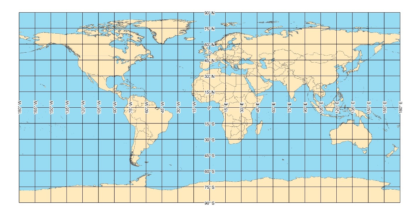
Figure: The map grid coordinate system
What is a Reference System?
A reference system is a framework used to define the position of objects in space. It provides a consistent set of coordinates and measurements, allowing for accurate representation and comparison of positions and movements. When dealing with high-precision systems, we must say which reference frame these coordinates are described in, and also at which epoch (what time) they are expressed.
What is a Reference Frame?
A geodetic reference frame serves as the practical realization of a reference system, offering a standardized set of coordinates for accurately determining locations on Earth and in space. By providing a reference surface, such as sea level, these frames enable precise positioning essential for tasks like surveying, mapping, and engineering. The International Terrestrial Reference Frame 2020 (ITRF2020) is a modern example, featuring 3D coordinates for stations worldwide. These fixed points, or “monumented points,” are carefully measured to support various applications and help geodetic experts understand the Earth’s dynamic processes.
Why are there Different Reference Frames?
While a geodetic reference system can be defined once and remains valid thereafter, this is not the case for a geodetic reference frame. The dynamic nature of the Earth’s crust means that points on its surface are constantly shifting due to tectonic plate movement and other sources of crustal deformation, such as earthquakes. In practical terms, within an Earth-Centered, Earth-Fixed (ECEF) reference frame like ITRF2020, the coordinates of surface points are continually changing.
It is for this reason that International Earth Rotation and Reference Systems Service (IERS) publishes station velocities along with station coordinates at a specified epoch for each realization of the frame. These velocities allow station coordinates to be moved through time within the reference frame, so long as the assumption of linear motion remains valid. However, the longer the time between the reference epoch and the computation date, the less accurate the propagated coordinates will be. This is why reference frames tend to have a year associated with them and new versions come up every few years (ITRF2014 -> ITRF2020)
Additionally, as time progresses, more stations can be incorporated into the reference frame solution, leading to the inclusion of improved observations, longer time series, and more sophisticated error modeling and computational methods. Consequently, each realization of the ITRF is more robust and accurate than its predecessor.
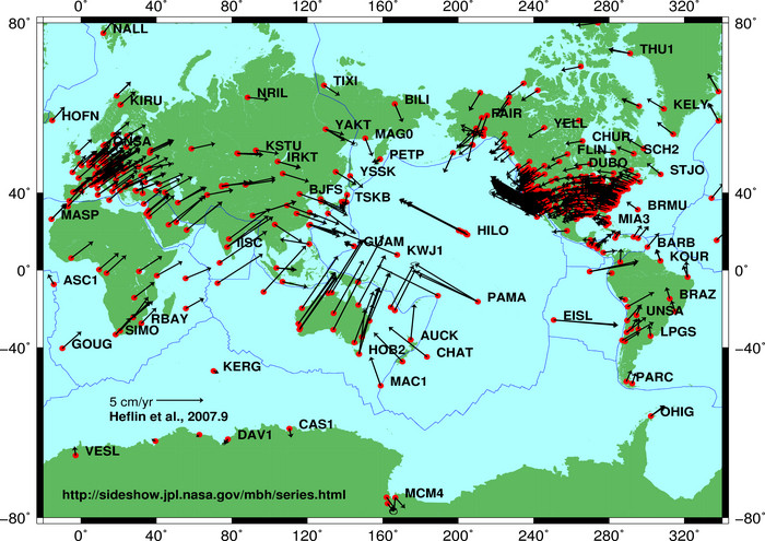
Figure: Depiction of tectonic plate movement from Heflin et al., 2007
Satellites in Global Navigation Satellite Systems (GNSS), like GPS, transmit their position in ECEF Cartesian coordinate systems, such as ITRF2020, which do not account for epoch. GNSS receivers calculate positions using these ECEF systems, which are effective for describing locations in space and air. However, on Earth, points shift over time relative to ECEF coordinates due to tectonic plate movement. For example, a fixed physical point, like a utility pole, will have changing x, y, z coordinates in the ITRF reference frame over time. Consequently, one must perform coordinate transformation.
Coordinate Transformation: Moving Between Frames and Epochs
Using an ECEF coordinate system for mapping an asset or rudimentary geospatial analysis works well for capturing relative position on Earth. However, it’s insufficient for navigation solutions that require precise, absolute positioning.
To solve this, surveyors and geodesy professionals use coordinate frames tied to tectonic plates, like the North American Datum of 1983 (NAD83) in the U.S. These plate-fixed systems ensure that positions relative to local geography remain stable over time. While NAD83 doesn’t perfectly account for tectonic drift, it offers much greater accuracy for precise positioning. However, this approach introduces a discrepancy: latitude, longitude, and altitude in ITRF2020 differ slightly from those in NAD83, and this difference varies over time. As a result, converting between these frames requires knowing the specific epoch, making it impossible to perform accurate translations without temporal context. This can be done through various transformations which we will explore below.
Temporal Transformation
Temporal transformation is the process of shifting coordinates from one epoch to another within the same reference frame; these transformations can be linear or non-linear. Linear temporal transformations account for tectonic plate motion, which is generally constant. However, non-linear motion, caused by factors like post-seismic relaxation or human activities (e.g., mining or oil extraction), requires more complex handling. Non-linear temporal transformation is less predictable and demands regional deformation models with high spatial and temporal resolution to capture the localized and dynamic nature of such movements.
Total temporal transformation combines both linear and non-linear components. Linear tectonic shifts move coordinates from one epoch to another, while non-linear changes are tracked through periodic measurements. These measurements are interpolated onto a grid, enabling a continuous deformation field representation. By adding deformation grids for each epoch, total deformation over time can be calculated accurately, offering a comprehensive view of both linear and non-linear movements in the Earth’s crust.
Spatial Transformation
Spatial transformations involve converting coordinates from one reference frame to another at a common epoch. Spatial conformal transformations preserve the relative shape and geometry of an object by applying a standard 7-parameter transformation (also known as Similarity, Conformal, or Helmert), typically without considering time variations. For instance, converting coordinates from ITRF2020 to ITRF2014 at a common epoch (e.g., 2010.0) requires only this conformal method to maintain geometric consistency across frames.
However, legacy reference frames often have spatial non-conformality due to historical limitations in measurement accuracy and computational methods. For example, the Australian Geodetic Datum 1966 (AGD66) used sparse data and older techniques, resulting in distortions not present in the more accurate Geocentric Datum of Australia 1994 (GDA94). To address this, a spatial non-conformal transformation uses a grid-based distortion model (e.g., NTv2 format) with 2D distortion components (Δ𝜙, Δ𝜆), which corrects these historic inaccuracies. This model allows for comprehensive transformations by combining both conformal and distortion elements in a single step.
Total spatial transformation involves applying both conformal and non-conformal components, often sequentially if more than one reference frame is involved. For instance, a two-stage transformation in Australia is needed to move from AGD66 to GDA2020 via GDA94. Unlike temporal transformations, these spatial distortions cannot simply be added across frames but must be applied step-by-step to retain accuracy. Over time, as outdated reference frames are phased out, the reliance on distortion models will gradually decrease.

Figure: The concept of a fully gridded transformation solution, with each component represented in gridded form and the total solution computed by sequential addition of the individual grids
Instead of having to perform these calculations yourself, often GIS software will convert between reference frames for you. For example, ArcGIS offers surveyors an easy way to transform from one reference frame to the other and supports a very wide combination of frames.
For a more detailed overview of coordinate conversion and transformation read our white paper, Practical Notes on Coordinate Transformation.
Get started https://account.swiftnav.com/sign-up

